Wire bonding is generally used for connecting the bond pads of a chip with the electrical contacts inside a housing, e. g. of a chip carrier, by means of a gold or aluminium bonding wire of just a few ten micrometers in thickness.
In essence, two procedures can be distinguished:
With wedge bonding, the bond wire is threaded through a capillary whose tip forms the wedge for bonding. The protruding wire is "melted" on the bonding pad by pressure, ultrasonic energy and heat (approx. 150°C; optional) and welded to the surface. The wire can then be fed to the next pad and welded there as well. After the second bond, the wire feed is blocked and the tail is broken off behind the welding point. A wire residue remains under the wedge of the capillary with which the next bonding process is started. The alignment of the remaining tail determines the direction of approach to the next bond pad.
Ball bonding is ultimately a variant of wedge bonding for gold wires in which the tail is melted by means of an electrical discharge for the first bond. This creates a ball at the end of the wire, which is pressed onto the bond pad with the capillary. Ball bonding simplifies the start-up of the first bond considerably, since it can be started up independently of the direction of the tail, which is otherwise typical for wedge bonding. However, this method poses higher demands on the quality of the bond pads and may require higher substrate temperatures.
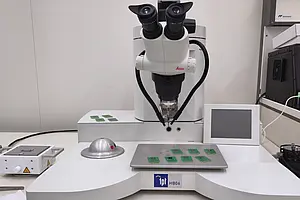
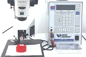
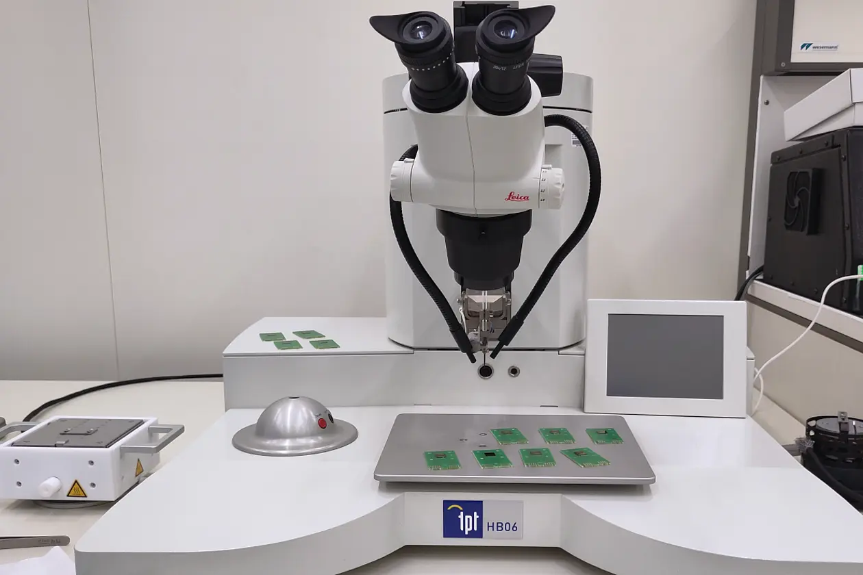
TPT HB06
The manual wedge-bonder HB06 can be used for very flexible bonding processes. The ultrasonic power, time and contact force for the first and second bond can be set separately, the temperature of the stage can be controlled from room temperature up to 250°C. Gold and aluminium wires with a diameter of 17 - 75 µm can be used. Bonding can be done down to a depth of 16 mm. The motorized z-axis can also be operated manually.